To define the CIM model (Analysis Layer models), we start describing the Social Model, then the Space and Task models.
Social Model
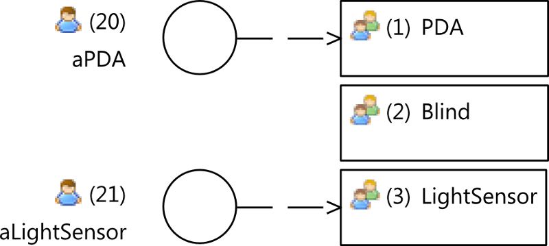
The Figure 30 depicts the social model of this scenario. It defines three roles:
- The Blind role represents the set of all blinds, Blind1-6 in the scenario.
- The PDA role represents the set of all PDAs in the system; a generic PDA is depicted into RoomA on the scenario.
- The LightSensor represents the set of all light sensors in the system. A light sensor provides the system of the awareness of light intensity in a room.
As an instance represents a single sample of a set of instances represented by a Role, this model describes two instances:
- The aPDA instance represents a PDA and it is used to reference a particular PDA in the system that was used to set light intensity in a room.
- The aLightSensor instance represents a LightSensor and it is used to refer to the light sensor of a room.
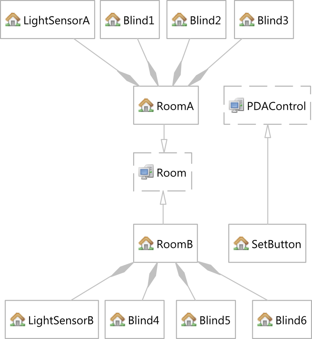
Space Model
The Light Controller scenario Space model is depicted in Figure 31. It represents two rooms RoomA and RoomB that are generalized by the Room virtual space.
Either, RoomA and RoomB are physically composed by blinds and sensors. RoomA is composed by blinds Blind1-3 and LightSensorA. And RoomB, and Blind4-6 and LightSensorB. The SetButton physical space is an interesting space defined on the PDA. It represents the area that is sensible to user stimulus when he/she wants to change the light intensity in the room.
Finally, the PDAControl virtual space represents the set of controls that are available on the PDA. In this case, we are only interested in the SetButton, but in order to provide extensibility we defined this virtual space.
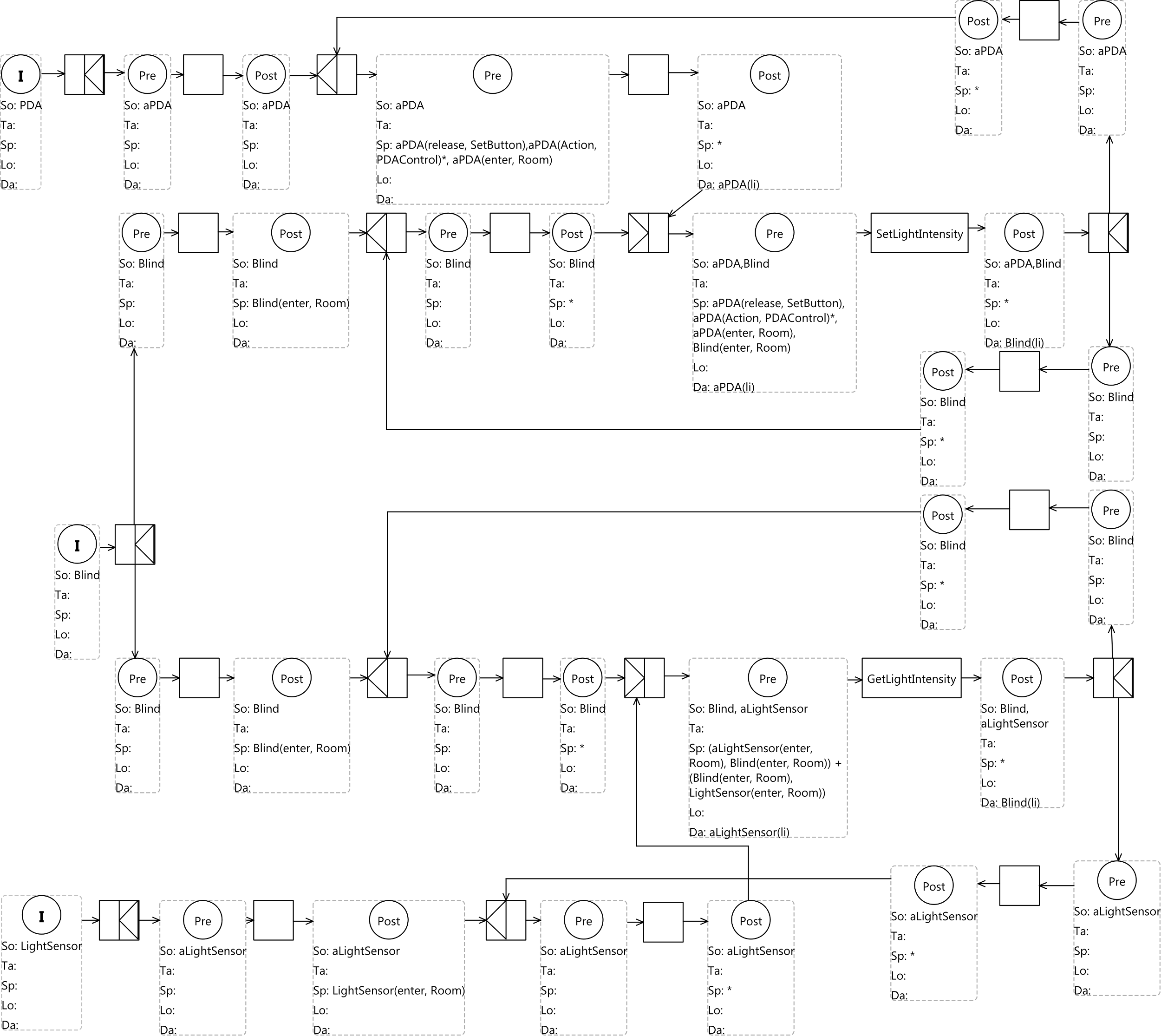
Task Model
We begin with the the Initial Condition that defines the PDA social expresion. This expression points out that the group of entities in this condition is represented by one token.
After the initialization, this group of PDAs arrives to a or-join route task. To go on, the instance represented by aPDA satisfies the following condition:
aPDA( release , SetButton ) ,aPDA( action , PDAControl) ∗ ,aPDA( enter , Room)
To satisfy this condition, aPAD should have enered the room, have performed one or more action on any of the PDAControls and have released the SetButton.
After, the condition is satisfied the aPDA instance waits to synchronize with a blind to communicate the li light intensity the user desires. This condition was defined after the and-split route task where the following condition must be satisfied by both, aPDA and the set of blinds Blind:
aPDA( action , PDAControl) ∗ , aPDA( enter , Room) , Blind ( enter , Room)
It means that the SetLightIntensity simple task is performed if and only if the set of blinds Blind that are in the room Room and the aPDA PDA that has entered the room a Room before a sequence of 0 or more actions on PDAControls.
Once, the SetLightIntensity task has finished; the and-split route task takes the token back for another task. Note that both post-conditions located after the and-split, clear the entity memory.
Next, we continue explaining the path followed by enties starting from the initial condition defining the Blind social expression.
Although, there are six tokens, one for each entity (blind), this expression points out that the group of entities in this condition is represented as one token. However, after the and-split route task, there are two tokens. one for each thread. It means that there are twelve threads running, two for each entity. If we follow the upper path of the Blind thread,the group of blinds perform the initialization process, until they arrive to an and-join route task. As in the aPDA path, to go through this point, the following condition must be satisfied:
aPDA( release , SetButton ) ,aPDA( action , PDAControl) ∗ ,aPDA( enter , Room)
The process from this point on is the same to the one exposed from the aPDA instance point of view.
An important issue to highlight is the going back path of the token. Note that it keeps on same path that was created for the thread. It means that no new tokens are created because of this action.
The last statement addresses the lack of the use of the final conditions, what are they used for?
The answer is simple; they are used as shortcuts to the initial condition. As we do not go back, we have not used them. However, they could have been used on two places:
- We could have replaced the go back tern (precondition, skip task, postcondition) by a final condition at the last and-split on the aPDA path.
- We also could have replaced the go back tern (precondition, skip task, postcondition) by a final condition of the last and-split on the aLightSensor path.
But, there is another question that is even more important to answer: where we should not use it?
The answer is related to the threading issue. Suppose that we define final conditions instead of the tern (precondition, skip task, postcondition) at the final and-split of both Blind paths. This
connection, leads to the introduction of two tokens instead of a single token that also leads to an overload of tokens. Another alternative is joining both threads on an and-join route task. But it prevents threads to run freely, leading to unnecessary stops.
Back to the threading procedure, we follow the lower path of the Blind thread. As in the upper path, the group of blinds follows the initialization process, until the group arrives to an and-join route task. To go through this point, the following condition must be satisfied.
( aLightSensor ( enter , Room) , Blind ( enter , Room) ) + ( Blind ( enter , Room) , LightSensor ( enter , Room) )
It means that the GetLightIntensity simple task is performed if and only if the set of blinds Blind that are in the room Room and the aLightSensor light sensor that is the room a Room get through each other. The + symbol establishes the order independence between Blind and LightSensor. It is not an important issue on this particular sample, but it may get complicated on more complex situations. So, sometimes the initialization order is set to static entities such as blinds and light sensors.
When the GetLightIntensity simple task is performed, the light intensity li is passed from the light sensor to the blinds. The rest of the circuit is the same as the upper path.
Finally, the analysis of the initial condition that defines the LightSensor social expression is very similar to the already exposed. It defines an initialization region and then it communicates to the blinds to provide it with the light intensity li.